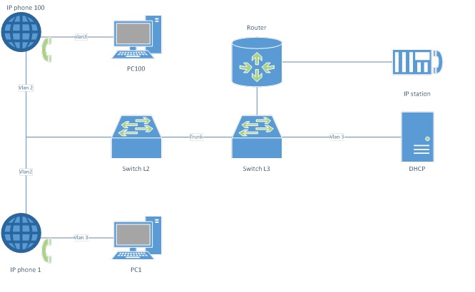
It seems like nothing is complicated. Vlans routing is being provided by Switch L3. PC1 – PC100 and DHCP server are included into Vlan 3. IP phone 1 – IP phone 100 are switched on Switch L2 by sending to it Vlan 3 traffic from PC and Vlan 2 traffic from IP phone. In our example we are using Cisco hardvare beside DHCP server and PC. On Switch L2 ports to which IP phone is being connected we set Voice vlan by using command:
switchport voice vlan 2
Vlan 3 for PC is also set on this switch ports. Other equipment may require different settings and connection schemes.
Cisco IP Phones use DHCP server to obtain IP addresses. IP phones and DHCP server are in different Vlans. We must route the request to obtain IP addresses. So we need to enter a command on the Vlan 2 interface of the Switch L3:
ip helper-address х.х.х.х
Where x.x.x.x is the IP address of the DHCP server that distributes the settings for our phones. By the way, there can be more than one address.
What happens in this case? To receive network settings, the phone sends a broadcast request to discover the DHCP server. When Switch L3 detects this request and sees the settings of the ip helper configured for Vlan 2, it takes this package to add additional information to it (for example, data about itself as the forwarding server, data on the sender address space taken from the settings of Vlan network interface in which sender is located) and sends to the address specified in the command ‘ip helper-address x.x.x.x’. DHCP server, having received this request, will process it and return the necessary parameters to the phone.
It would seem. Correctly configured DHCP server, preconfigured phone, one command on Switch L3 and-and-and … it nothing works. After spending some time studying the settings of everything that is possible, reading the Internet articles and descriptions, we accidentally found one small command for Switch L3:
service dhcp
and it is all working.
